Plant Engineering

Plant engineering is that branch of engineering which embraces the installation, operation, maintenance, modification, modernization, and protection of physical facilities and equipment used to produce a product or provide a service. It is easier to describe plant engineering than to define it. Yet, the descriptions will vary from facility to facility and over time. Every successful plant is continuously changing, improving, expanding, and evolving. And the activities of the plant engineer must reflect this environment. Each plant engineer is likely to have his own, unique job description, and that description is likely to be different from the one he had five years earlier. 

By definition, the plant engineering function is multidisciplinary. It routinely incorporates the disciplines of mechanical engineering, electrical engineering, and civil engineering. Other disciplines, such as chemical engineering for example, may also be needed, depending on the type of industry or service involved. In addition, skills in business/financial management, personnel supervision, project management, contracting, and training are necessary to the successful fulfillment of plant engineering responsibilities. The function is fundamentally a technical one, requiring a thorough technical/engineering background through education and/or experience. But beyond it’s most basic level, a broad range of skills is needed. If the plant engineer is a specialist in anything, it is in his/her own plant or facility. 

Plant engineers must learn to know their own plants thoroughly, from the geology underlying its foundations and the topology of the rainwater runoff to the distribution of its electricity and the eccentricities of its production machinery. They must ensure the quality of the environment both inside and outside the facility as well as the safety and health of the employees and the reliability of its systems and equipment. And they are expected to do all of this in a cost-effective manner. A few phrases from a 1999 classified ad for a plant engineer provide some real-world insight on the scope of responsibilities: 

  • Support ongoing operations, troubleshoot, resolve emergencies, implement shutdowns
  • Organize and maintain information on plant systems/equipment and improvement programs
  • Implement plant projects and maintain proper documentation 
  • Deal effectively with multiple activities, requests, and emergencies
  • Manage scope, design, specification, procurement, installation, startup, debugging, validation, training, and maintenance

To this list, most plant engineers would quickly add compliance with all applicable laws and regulations as well as accepted industry standards and practices. 

The primary mission of the plant engineer is to provide optimum plant and equipment facilities to meet the established objective of the business. This can be broken down into these four fundamental activities: 

(1) ensure the reliability of plant and equipment operation; 

(2) optimize maintenance and operating costs; 

(3) satisfy all safety, environmental, and other regulations; and 

(4) provide a strong element of both short term and long-range facilities and equipment planning.’ 

The description still rings true today

Fault Tree for Air Compressor Explosion


Goals of risk analysis


A risk analysis can have a variety of potential goals:

1.          To screen or bracket a number of risks in order to prioritize them for possible future study

2.          To estimate risk to employees

3.          To estimate risk to the public

4.          To estimate financial risk

5.          To evaluate a range of risk reduction measures

6.          To meet legal or regulatory requirements

7.          To assist in emergency planning

Qualitative Tools for Hazard Analysis

SHEL (Safety, Health, Environmental, and Loss Prevention Reviews) These reviews are performed during design. The purpose of the reviews is to have an outsider’s evaluation of the process and layout from safety, industrial hygiene, environmental, and loss prevention points of view. It is often desirable to combine these reviews to improve the efficiency of the use of time for the reviewers.

Checklists Checklists are simple means of applying experience to designs or situations to ensure that the features appearing in the list are not overlooked. Checklists tend to be general and may not be appropriate to a specific situation. They may not handle adequately the novel design or unusual process.

What-if At each process step, what-if questions are formulated and answered to evaluate the effects of component failures or procedural errors. This technique relies on the experience level of the questioner.

Failure Mode and Effect Analysis (FMEA) This is a systematic study of the causes of failures and their effects. All causes or modes of failure are considered for each element of a system, and then all possible outcomes or effects are recorded. This method is usually used in combination with fault tree analysis, a quantitative technique. FMEA is a complicated procedure, usually carried out by experienced risk analysts.

Cause-Consequence Diagram These diagrams illustrate the causes and consequences of a particular scenario. They are not widely used because, even for simple systems, displaying all causes and outcomes leads to very complex diagrams. Again, this technique is employed by experienced risk analysts.

Reactive Chemicals Reviews The process chemistry is reviewed for evidence of exotherms, shock sensitivity, and other instability, with emphasis on possible exothermic reactions. It is especially important to consider pressure effects—“Pressure blows up people, not temperature!” The purpose of this review is to prevent unexpected and uncontrolled chemical reactions. Reviewers should be knowledgeable people in the 

Industrial Hygiene Reviews These reviews evaluate the potential of a process to cause harm to the health of people. It is the science of the anticipation, recognition, evaluation, and control of health hazards in the environment. It usually deals with chronic, not acute, releases and is involved with toxicity.

Toxicity is the ability to cause biological injury. Toxicity is a property of all materials, even salt, sugar, and water. It is related to dose and the degree of hazard associated with a material. The amount of a dose is both time and duration dependent. Dose is a function of exposure (concentration) and duration and is sometimes expressed as dose = (concentration)n × duration, where n can vary from 1 to 4.

Industrial hygiene deals with hazards caused by chemicals, radiation, and noise. Routes of exposure are through the eyes, by inhalation, by ingestion, and through the skin. An industrial hygiene guide is based on exposures for an 8-hour day, 40-hour week and is to be used as a guide in the control of health hazards. It is not to be used as a fine line between safe and dangerous conditions. Types of controls used include:

Engineering, such as containment, ventilation, and automation

Administrative, such as use of remote areas and job rotation

Protective equipment


HAZOP

HAZOP stands for “hazard and operability studies.” This is a set of formal hazard identification and elimination procedures designed to identify hazards to people, process plants, and the environment. The techniques aim to stimulate in a systematic way the imagination of designers and people who operate plants or equipment so they can identify potential hazards. In effect, HAZOP studies make the assumption that a hazard or operating problem can arise when there is a deviation from the design or operating intention. Corrective actions can then be made before a real accident occurs.

Some studies have shown that a HAZOP study will result in recommendations that are 40 percent safety-related and 60 percent operability-related. HAZOP is far more than a safety tool; a good HAZOP study also results in improved operability of the process or plant, which can mean greater profitability.

The primary goal in performing a HAZOP study is to identify, not analyze or quantify, the hazards in a process. The end product of a study is a list of concerns and recommendations for prevention of the problem, not an analysis of the occurrence, frequency, overall effects, and the definite solution. If HAZOP is started too late in a project, it can lose effectiveness because:

1.               There may be a tendency not to challenge an already existing design.

2.               Changes may come too late, possibly requiring redesign of the process.

3.               There may be loss of operability and design decision data used to generate the design.

HAZOP is a formal procedure that offers a great potential to improve the safety, reliability, and operability of process plants by recognizing and eliminating potential problems at the design stage. It is not limited to the design stage, however. It can be applied anywhere that a design intention (how the part or process is expected to operate) can be defined, such as:

            Continuous or batch processes being designed or operated

            Operating procedures

            Maintenance procedures

            Mechanical equipment design

            Critical instrument systems

            Development of process control computer codeThese studies make use of the combined experience and training of a group of knowledgeable people in a structured setting. Some key concepts are:

            Intention—defines how the part or process is expected to operate.

            Guide words—simple words used to qualify the intention in order to guide and stimulate creative thinking and so discover deviations. Table 26-2 describes commonly used guide words.

Deviations—departures from the intention discovered by 

            Causes—reasons that deviations might occur.

            Consequences—results of deviations if they occur.

            Actions—prevention, mitigation, and control —Prevent causes.

—Mitigate the consequence.

—Control actions, e.g., provide alarms to indicate things getting out of control; define control actions to get back into control.

The HAZOP study is not complete until response to actions has been documented. Initial HAZOP planning should establish the management follow-up procedure that will be used.

The guide words can be used on broadly based intentions (see Table 26-2), but when intentions are expressed in fine detail, some restrictions or modifications are necessary for chemical processes, such as:

No flow

Reverse flow

Less flow

More temperature

Less temperature

Composition change

Sampling

Corrosion/erosion

This gives a process plant a specific HAZOP guide-word list with a process variable, plant condition, or an issue.

HAZOP studies may be made on batch as well as continuous processes. For a continuous process, the working document is usually a set of flow sheets or piping and instrument diagrams (P&IDs). Batch processes have another dimension: time. Time is usually not significant with a continuous process that is operating smoothly except during start-up and shutdown, when time will be important and it will resemble a batch process. For batch processes, the working documents consist not only of the flow sheets or P&IDs but also the operating procedures. One method to incorporate this fourth dimension is to use guide words associated with time, such as those described in Table 26-3.

HAZOP studies involve a team, at least some of whom have had experience in the plant design to be studied. These team members apply their expertise to achieve the aims of HAZOP. There are four overall aims to which any HAZOP study should be addressed:

1.               Identify as many deviations as possible from the way the design is expected to work, their causes, and problems associated with these deviations.

2.               Decide whether action is required, and identify ways the problem can be solved.

3.               Identify cases in which a decision cannot be made immediately and decide what information or action is required.

4.               Ensure that required actions are followed through.

The team leader is a key to the success of a HAZOP study and should have adequate training for the job. Proper planning is important to success. The leader is actually a facilitator (a discussion leader and one who keeps the meetings on track) whose facilitating skills are just as important as technical knowledge. The leader outlines the boundaries of the study and ensures that the design intention is clearly understood. The leader applies guide words and encourages the team to discuss causes, consequences, and possible remedial actions for each deviation. Prolonged discussions of how a problem may be solved should be avoided.

Facilities Reviews

 There are many kinds of facilities reviews that are useful in detecting and preventing process safety problems. They include 

  1. pre-start-up reviews (before the plant operates),
  2. new plant reviews (the plant has started, but is still new), 
  3. reviews of existing plants (safety, technology, and operations audits and reviews), 
  4. management reviews, 
  5. critical instrument reviews, and 
  6. hazardous materials transportation reviews.

Knowledge Organization

 INSTITUTIONAL MEMORY

Most accidents do not occur because we do not know how to prevent them but because we do not use the information that is available. The recommendations made after an accident are forgotten when the people involved have left the plant; the procedures they introduced are allowed to lapse, the equipment they installed is no longer used, and the accident happens again. The following actions can prevent or reduce this loss of information.

             Include a note on “the reason why” in every instruction, code, and standard, and accounts of accidents which would not have occurred if the instruction, code, or standard had been followed.

             Describe old accidents, as well as recent ones, in safety bulletins and newsletters and discuss them at safety meetings.

             Follow up at regular intervals (for example, during audits) to see that the recommendations made after accidents are being followed, in design as well as operations.

             Make sure that recommendations for changes in design are acceptable to the design organization. On each unit keep a memory book, a folder of reports on past accidents, which is compulsory reading for new recruits and which 

             others dip into from time to time. It should include relevant reports from other companies but should not include cuts and bruises.

             Never remove equipment before you know why it was installed. Never abandon a procedure before you know why it was adopted.

             Devise better information retrieval systems so that details of past accidents, in our own and other companies, and the recommendations made afterward are more easily accessible than at present.

             Include important accidents of the past in the training of young graduates and company employees. 


INCIDENT INVESTIGATION AND HUMAN ERROR

Although most companies investigate accidents (and many investigate dangerous incidents in which no one was injured), these investigations are often superficial, and we fail to learn all the lessons for which we have paid the high price of an accident. The facts are usually recorded correctly, but often only superficial conclusions are drawn from them. Identifying the causes of an accident is like peeling an onion. The outer layers deal with the immediate technical causes and triggering events while the inner layers deal with ways of avoiding the hazard and with the underlying weaknesses in the management system (Kletz, Learning from Accidents, 2d ed., Butterworth-Heinemann, 1994).

Dealing with the immediate technical causes of a leak, for example, will prevent another leak for the same reason. If so little of the hazardous material can be used that leaks do not matter or a safer material can be used instead, as previously discussed, all significant leaks of this hazardous material can be prevented. If the management system can be improved, we may be able to prevent many more accidents of other sorts.

Other points to watch when drawing conclusions from the facts are:

1. Avoid the temptation to list causes we can do little or nothing about. For example, a source of ignition should not be listed as the primary cause of a fire or explosion, as leaks of flammable gases are liable to ignite even though we remove known sources of ignition. The cause is whatever led to the formation of a flammable mixture of gas or vapor and air. (Removal of known sources of ignition should, however, be included in the recommendations.) Similarly, human error should not be listed as a cause. 

2. Do not produce a long list of recommendations without any indication of the relative contributions they will make to the reduction of risk or without any comparison of costs and benefits. Resources are not unlimited and the more we spend on reducing one hazard, the less there is left to spend on reducing others.

3. Avoid the temptation to overreact after an accident and install an excessive amount of protective equipment or complex procedures which are unlikely to be followed after a few years have elapsed. Sometimes an accident occurs because the protective equipment available was not used; nevertheless, the report recommends installation of more protective equipment; or an accident occurs because complex procedures were not followed and the report recommends extra procedures. It would be better to find out why the original equipment was not used or the original procedures were not followed. 

4. Remember that few, if any, accidents have simple causes.

5. When reading an accident report, look for the things that are not said. For example, a gland leak on a liquefied flammable gas pump caught fire and caused considerable damage. The report drew attention to the congested layout, the amount of redundant equipment in the area, the fact that a gearbox casing had been made of aluminum, which melted, and several other unsatisfactory features. It did not stress that there had been a number of gland leaks on this pump over the years, that reliable glands are available for liquefied gases at ambient temperatures, and, therefore, there was no need to have tolerated a leaky pump on this duty.

As another example, a fire was said to have been caused by lightning. The report admitted that the grounding was faulty but did not say when it was last checked, if it was scheduled for regular inspection, if there was a specification for the resistance to earth (ground), if employees understood the need for good grounding, and so on.

6. At one time most accidents were said to be due to human error, and in a sense they all are. If someone—designer, manager, operator, or maintenance worker—had done something differently, the accident would not have occurred. However, to see how managers and supervisors can prevent them, we have to look more closely at what is meant by human error:

a.           Some errors are due to poor training or instructions: someone did not know what to do. It is a management responsibility to provide good training and instructions and avoid instructions that are designed to protect the writer rather than help the reader. However many instructions are written, problems will arise that are not covered, so people—particularly operators—should be trained in flexibility—that is, the ability to diagnose and handle unforeseen situations. If the instructions are hard to follow, can the job be simplified?

b.           Some accidents occur because someone knows what to do but makes a deliberate decision not to do it. If possible the job should be simplified (if the correct method is difficult, an incorrect method will be used); the reasons for the instructions should be explained; checks should be carried out from time to time to see that instructions are being followed; and if they are not, this fact should not be ignored.

c.            Some accidents occur because the job is beyond the physical or mental ability of the person asked to do it—sometimes it is beyond anyone’s ability. The plant design or the method of working should be improved.

d.           The fourth category is the commonest: a momentary slip or lapse of attention. They happen to everyone from time to time and cannot be prevented by telling people to be more careful or telling them to keep their minds on the job. All that can be done is to change the plant design or method of working to remove opportunities for error (or minimize the consequences or provide opportunities for recovery). Whenever possible, user-friendly plants (see above) should be designed which can withstand errors (and equipment failures) without serious effects on safety (and output and efficiency).


Plant Design for Safety—A User-Friendly Approach,

Intensification This involves using so little hazardous material that it does not matter if it all leaks out. For example, at Bhopal, methyl isocyanate (MIC), the material that leaked and killed over 2000 people, was an intermediate for which it was convenient but not essential to store. Within a few years many companies had reduced their stocks of MIC and other hazardous intermediates.

As another example, at one time nitroglycerin (NG) was manufactured in batch reactors containing about a ton of raw materials and product. If the reactor got too hot, there was a devastating explosion. In modern plants, NG is made in a small continuous reactor containing about a kilogram. The severity of an explosion has been reduced a thousandfold, not by adding on protective devices, which might fail or be neglected, but by redesigning the process. The key change was better mixing, achieved not by a better stirrer, which might fail, but by passing one reactant (acid) through a device like a laboratory water pump so that it sucks in the other reactant (glycerin) through a sidearm. If the acid flow stops, the glycerin flow also stops, not through the intervention of a flow controller, which might fail, but as an inevitable result of the laws of physics (Bell, Loss Prevention in the Process Industries, Institution of Chemical Engineers Symposium Series No. 34, 1971, p. 50).

Intensification is the preferred route to inherently safer design, as the plants, being smaller, are also cheaper.

Substitution If intensification is not possible, then an alternative is to consider using a safer material in place of a hazardous one. Thus it may be possible to replace flammable solvents, refrigerants, and heat-transfer media by nonflammable or less flammable (highboiling) ones, hazardous products by safer ones, and processes which use hazardous raw materials or intermediates by processes which do not. As an example of the latter, the product manufactured at Bhopal (carbaryl) was made from three raw materials. Methyl isocyanate is formed as an intermediate. It is possible to react the same raw materials in a different order so that a different and less hazardous intermediate is formed.

Attenuation Another alternative to intensification is attenuation, using a hazardous material under the least hazardous conditions. Thus large quantities of liquefied chlorine, ammonia, and petroleum gas can be stored as refrigerated liquids at atmospheric pressure instead of storing them under pressure at ambient temperature. (Leaks from the refrigeration equipment should also be considered, so there is probably no net gain in refrigerating quantities less than a few hundred tons.) Dyestuffs which form explosive dusts can be handled as slurries.

Process Safety Awareness

  1.  Increase of concern due to numbers of accidents involve 
    • Gas releases
    • Major explosions
    • Environmental incidents
  2. Hazard of the chemical plant
    • Damage & loss of life
    • Vapor cloud explosions
    • Sudden pressure release
    • Static electricity as hidden cause
    • Reactive nature of chemical
    • Loss of containment due to mechanical failure or miss operation
  3. Process Safety Analysis
    1. Hazard analysis
    2. Risk analysis
    3. Guidelines for estimating damage
    4. Project review and procedures
  4. Safety Devices
    1. Pressure relief devices
    2. Flame arresters
    3. Effluent handling
    4. Highly toxic & hazardous chemical handling & storage
  5. Hazardous Materials and Conditions
    1. Reactive
    2. Combustion and flammability hazards
    3. Gas explosions
    4. Unconfined vapor explosions (UVCEs) and Boiling Liquid Evaporating Vapor Explosions (BLEVEs)
    5. Dust explosions
    6. Static electricity
    7. Hazards of vacuum
    8. Hazard of Inert Gases
    9. Gas Dispersion
    10. Discharge rates from punctures lines and vessels

Disaster of Chemical Plant at Flixborough

 Ref

http://www.shippai.org/fkd/en/cfen/CB1058048.html

June,1,1974

Flixborough, UK

Cyclohexanone Oxidation Plant

Temperary bypass pipe for reactor and process pipe between separators

Overview

The Flixborough Works of Nypro (UK) Ltd. were demolished at about 4:53 p.m. on Saturday June 1st. 1974, by an explosion of warlike dimensions which was the equivalent of 15 tonnes of TNT. Of those working on the site at the time, 28 were killed and 36 others suffered injuries. Outside the works injuries and damage were widespread. 53 people were recorded as casualties, while 1,821 houses and 167 shops and factories suffered damage to a greater or lesser degree. The plant at which the explosion occurred was part of a complex for the manufacture of nylon, jointly owned by Dutch State Mines (55%) and UK National Coal Board (45%).

Incident

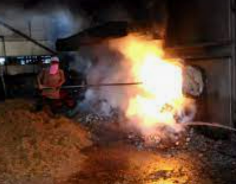
The reaction was cyclohexane with air under existence catalysis by 155°C, 125 lb/sq.in. (0.86 MPa), to a mixture of cyclohexanone and cyclohexanol that is usually known as KA (ketone/alcohol) mixture. The reaction took place in six vessels, each holding about 20 tonnes. One of the reactors, the No.5 reactor, developed a crack and was removed for repair. In order to maintain production, a temporary bypass pipe was installed between the No.4 reactor and the No.6 reactor. Because the reactors were mounted on a sort of staircase, this pipe was not straight but contained two bends. The pipe was 20in. (508 mm) in diameter, although the short pipes that were normally used to join the reactor together were 28in. (711 mm) in diameter. Bellows also 28 in.(711 mm) in diameter, were installed between each reactor, and these were left at each end of the temporary pipe. This temporary bypass pipe performed satisfactorily for two months after the plant was restarted on April 1st. However, the process pressure rose slightly, from 125 lb/sq.in. (0.86 MPa) to 129 lb/sq.in. (0.89 MPa ). The bending moment, caused by the action of this slight rise in pressure, was strong enough to tear the bellows. The temporary pipe acted to twist the flow, and the bellows were ruptured by shear stress. As a result of the rupture of the bellows, a great amount of cyclohexane escaped from the holes in the bellows and formed a cloud of cyclohexane vapour, which subsequently caused the explosion (Fig. 2). This explosion killed 28 men were and injured 36 men on site. The oxidation unit and neighboring units were destroyed and extensive damage was caused to the rest of the site. In particular, the company office block, about 100 m away, was destroyed. An initial investigation at the site found a "S" shape 20in. (508 mm) pipe assembly lying on the concrete plinth below its original position. It had jack-knifed completely at the lower mitre joint and apparently collided violently with the plinth after being projected forcibly downwards. Both of the bellows had torn away from the temporary pipe. They had also been torn off the reactor nozzles. Each of the bellows had disintegrated into a few large pieces, all of which were found in the vicinity of the failed pipe. In addition, the initial investigation revealed that a 50 in. (1270 mm) split had occurred in the bend in an 8 in. (203 mm) diameter stainless steel pipe joining two nearby separators.

Sequence

The cyclohexane oxidation process was performed in a series of six reactors, each holding about 20tonnes. The reactors were about 12feet (3658mm) in diameter and 16feet (4877mm) high, and they were constructed of 1/2in. (13mm) mild steel, with internal cladding of 1/8in. (3mm) stainless steel (type 316L).
After fresh cyclohexane and recycle cyclohexane were scrubbed with water in a cooling scrubber, they were heated in a direct heat exchanger. Subsequently, both forms of cyclohexane were introduced into the No.1 reactor and oxidized to a mixture of cyclohexanone and cyclohexanol, usually known as KA (ketone/alcohol), with air under the existence of a catalyst, at 155degree C and 125lb/sq.in. (0.85 MPa).
At the end of March 1974, the No.5 reactor was found to be leaking, and an inspection showed a crack over 6feet (1830mm) long in the mild steel. Subsequent examination of the crack by Dutch State Mines (DSM) determined the cause of the failure to be nitrate stress corrosion cracking of the mild steel cladding. This nitrate stress corrosion cracking was believed to have been due to the practice of spraying nitrate-treated cooling water as a means for diluting and dispersing small leaks.
It was decided to remove the No.5 reactor, put in a temporary bypass pipe, and restart the plant. The bypass consisted of a dog-leg pipe from 20in. (508mm) diameter 304L stainless steel, installed between two expansion bellows that were attached to the 28in. (711mm) diameter nozzles after the reactor removal. The bypass was never closely inspected, although at operating temperatures and pressures, it was observed to lift off the scaffolding supports that were put in during the installation.
After the plant was restarted on April 1st.initially this temporary pipe connection functioned satisfactorily. However, on May 29th, a leak was found on sight glass, and the plant was shut down for repairs. An attempt to restart the plant was made at 4:00 a.m. on June 1st. More leaks were found, and after fixing these and restarting, the pressure was noted to rise more quickly than usual to 125lb/sq.in. (0.86MPa) gauge, well before the first reactor had reached operating temperature. Before any venting took place, however, another leak developed, the heating was stopped, and the pressure dropped to 64lb/sq.in. (0.44MPa) gauge.
The 7:00 a.m. to 3:00 p.m. shift fixed the leak and began warming the reactors up at 9:30 a.m., needing to vent only once at 11:30 a.m. when the pressure had reached 129lb/sq.in. (0.89MPa) gauge, but did not vent. The nitrogen stock for purging was found to be insufficient, however, and as a fresh delivery was not expected before midnight, the system was kept on "dry-cycling", i.e., recycling of hot cyclohexane under pressure but with no admission of air for reaction. At the end of the 7:00 a.m. to 3:00 p.m. shift, the temperatures in the reactor system had not leveled out.
The temporary pipe was deformed in a "V" shape by bending stress at only slightly above operating pressure, and the bellows, the weak link in the chain, were torn away by shear stress. As a result, a massive vapor cloud was formed by the escape of cyclohexane from the holes of the ruptured 28in. (711mm) diameter bellows, and subsequent ignition caused the explosion to occur.
The explosion, which occurred 4:53 p.m., was estimated to have an equivalent force of at least 15tonnes of TNT. What happened on the final shift can never be known because all those in the control room were killed and all instrumentation and records were destroyed. The explosion also destroyed the oxidation units and neighboring units and caused extensive damage to the rest of the site.
The initial site investigation had revealed a 50in. (1270mm) split had occurred in the bend in an 8in. (203mm) diameter stainless steel pipe joining two nearby separators. A leak occurred at a flange on the non-return valve, located near this 50in. (1270mm) split. As a result, spontaneous combustion or a spray which were ignited by induced electrostatic charge, the result being a flame directed into the inside of an 8in. (203mm) bend.
After the explosion, a metallurgical investigation of the 8in. (203mm) line yielded considerable data concerning the effects of zinc embrittlement and creep cavitation at high temperatures on austenitic stainless steel.
At first, it was assumed that the assembly failed as a result of a small external explosion following the prior rupture of a nearby 8in. (203mm) line. However, this theory was rejected by the Court.

Cause

After the No.5 reactor was removed for repair, a temporary bypass pipe was installed between the No.4 reactor and the No.6 reactor. The bypass pipe required an "S" shape, because the reactors were mounted on a sort of staircase.
The reason for why the bellows fractured by shear stress, was that the temporary pipe was installed without examining what the effect of a slight pressure rise on the bellows would be.
The workers who designed the temporary pipe were not professional engineers. The only calculations made were of the capacity of the assembly needed to carry the required flow. No calculations were done to ascertain whether the bellows or pipe would withstand the forces that would be exerted. No reference was made to the relevant British Standard or any other accepted standard. No reference was made to the designer's guide issued by the manufacturers of the bellows. No drawing of the pipe was made, other than in chalk on the workshop floor.
The support of the temporary pipe was a scaffolding structure upon which the pipe rested, without being fastened down. Therefore, the support structure could be provide not enough strength to withstand against bending stress.
The source of ignition was probably a natural gas reforming furnace some distance away. It was estimated that 30-50 tonnes of cyclohexane escaped in the 50 seconds that elapsed before ignition occurred.
Besides these details, the initial site investigation revealed that a 50in.(1270mm) split had occurred in the bend in an 8in. (203mm) diameter stainless steel pipe joining two nearby separators. The cause of this split is as follows. A leak occurred as a result of two loose bolts at a flange on the non-return valve, located near the 50in. (1270mm) split. This leak gave rise to an accumulation of oxidizable residues in the lagging and spontaneous combustion or a spray which was ignited by induced elctrostatic charges; the result being a flame directed into the inside of an 8in. (203mm) bend. It was assumed that the 50in. (1270mm) split occurred by zinc embrittlement and creep cavitation at high temperatures. This assumption was later confirmed by a metallurgical investigation showing that zinc embrittlement on austenitic stainless steel at a temperature of between 800 and 900 degree C could occur in a pipe under a stress of 3.21ton/sq.in. (48.8N/sq.mm) within a few seconds. The possible sources of zinc that could cause such an embrittlement attack were the galvanized stairways and the wire securing the lagging. Furthermore, it was shown that rapid creep cavitation of stainless steel may occur within minutes at temperatures of 950 degree C or more and under a stress of 4.7ton/sq.in. (71.4N/sq.mm).
In regard to the failure of the temporary pipe and an 8in. (203mm) pipe, it was supposed that the assembly failed as a result of a small external explosion following prior rupture of a nearby 8in. (203mm) pipe. However, the Court concluded that both phenomena occurred as a result of a sequence of improbabilities and coincidences.

Response

Immediately after this disaster occurred, UK government ordered that a formal investigation be carried out by a Court of Inquiry, consisted of a panel of experts.
Experimental work, which included a full scale simulation was carried out at Flixborough. These tests showed that the bellows squired into on "S" shape at a pressure only slightly above the operating pressure.
Calculations of flow through the28 in. (711mm) diameter open nozzles of the two reactors supported the view that the release of the cloud of cyclohexane vapour of sufficient size to cause the disaster rapidly followed the collapse of the temporary pipe. It is almost impossible to prevent ignition of a leak the size of that which occurred at Flixborough. However, it is possible to locate and layout a plant so that injuries and damage are minimized if an explosion occurs. It was suggested that a diagram be made of the relation between the distance from the point of release and the size of the cloud (tonnes of hydrocarbon equivalent) at the plant containing materials that might explode. This diagram shows the restriction on design divided into six areas: A-F. For example, area A, the region within 20m from the point of release, should not contain any buildings at all. In area B, there should not be any other hazardous plants or site roads. In area C, there should not be any low pressure tanks. In area D, roofs of buildings should be independently supported and windows protected, and there should not be any public roads. In area E, there should not be any houses, and as for area F, there are no limitations on design.

Countermeasures

Because the plant suffered wide-scale destruction, the first step of the countermeasure was to rebuild the plant according to the lessons learned from the disaster. In this case, it was necessary to consider the improvement of the production process. Because the production process was a high inventory process, if a leak occurred, the plant would suffer a great amount of damage. Therefore, if the production process were designed for inventory reduction, then it might be possible to minimize the damage.
In fact, the production process for manufacturing cyclohexanol was changed from the oxidation of cyclohexane to the hydrogeneration of phenol. However, this process is at least as hazardous.

Knowledge Comment

It was well known to metallurgists that water contained nitrates causes stress corrosion cracking of mild steel. The decision that nitrate treated cooling water be sprayed on the top of the reactor, was made by persons who were not very knowledgeable. In fact, the decision was hardly known to the engineers.
No change in the operating condition outside the approved range should be made until they have been authorised by a professionally qualified manager.
After the reactor was removed, the temporary bypass pipe was designed and installed by mechanical engineers who were not professionally qualified because of the desire to quickly restore production.
No calculations were done to ascertain whether or not the bellows or the temporary pipe would be able to withstand the strains that would occur as a result of a slight rise in pressure. Also, the supports were not strong enough to withstand the bending stress of the pipe. Consequently, the bending moment caused by a slight rise in pressure was sufficient to cause the temporary pipe to tear the bellows.
Especially in plants that are treating hazardous materials, even relatively easy repairs or improvements of facilities should be made with thorough reference to the standards, and the design should be entrusted to professional engineers.
Occasionally, a large disaster can occur as a result of hot gas spouting to another piece of equipment, such as the gas that leaked from the 50in. (1270mm) split in the bend in an 8in. (203mm) diameter stainless steel pipe joining two nearby separators. So,it is necessary to consider methods for detecting and preventing leaks.
For plants containing materials that might explode, the safety of the plant layout and equipment location should be considered. For instance, no buildings should be within 20m of plant, and the construction of occupied buildings near the plant, should be strengthened.
On account of the high inventory of the production process at Flixborough, a large amount of cyclohexane escaped and caused a large scale explosion. If the plant had applied a low inventory process, a large scale explosion would not occur. It was not known why Flixborough adopted a high inventory process. Howevewr, when investigating the process operated at Flixborough, the output of the plant was found to be about 50,000tonnes/year KA. Assuming a linear velocity of 0.5m/s, it could all have passed through a pipe 1.6in. (40.6mm) in diameter. The actual pipe sizes ranged up to 28in. (711mm), so the cross section of the pipe, and thus the flow rate, was (28/1.6)^2 = 300 times greater than the theoretical minimum diameter required to support the plant output.

Sequel

In the UK, the government set up an Advisory Committee on Major Hazards to consider the wider implications of the Flixborough explosion. It took about ten years for their recommendations to be made and to come into force. The recommendation of the committee resulted in the establishment of the CIMAH (Control of Industrial Major Account Hazards). The regulations have now been replaced by the COMAH (Control of Major Accident Hazards).
The plant changed its production process for manufacturing cyclohexanon and cyclohexanol from the oxidation of cyclohexane to the hydrogeneration of phenol. However, the rebuilt plant as closed down, after a few years, for commercial reasons.

Number of deaths : 28

Number of injuries : 89

Author : Shinohara, Takanori & Kobayashi, Hideo

The Start of Process Safety Management: The Flixborough Disaster – June 1, 1974 by Inspector Frank blog


Reference

https://inspectioneering.com/blog/2022-02-24/10030/lets-be-frank-the-start-of-process-safety-management-the-flixborough-disaster

It was a failure of the cyclohexane plant that led to the explosion that occurred at 1653 hours on Saturday, June 1st, 1974.

A major leak of liquid from the reactor circuit led to the rapid formation of a large cloud of flammable hydrocarbon. When this met an ignition source (probably a furnace at a nearby hydrogen reformer), there was a massive fuel-air explosion. The plant control room collapsed, killing all 18 occupants. Nine other site workers were killed, and a delivery driver died of a heart attack in his cab. 28 were killed onsite, and 36 more were injured. Offsite, 53 additional people were injured. Fires started on-site which were still burning ten days later. Around 1,000 buildings within a mile radius of the site were damaged, as were nearly 800 in Scunthorpe (three miles away); the blast was heard over thirty-five miles away.

I have started using the Flixborough disaster as a safety talk topic, even though the disaster happened almost 48 years ago. Why? Because people forget, and it is still a good set of lessons to learn. This incident has long been held as one of the big events that drove the concept of process safety management (PSM) forward. First in Europe, and then around the rest of the world. I have been finding Flixborough useful to get people engaged in discussing PSM, and in getting junior inspectors interested in learning why the systems they are using and taking part in even exist.

Plus: being humans, we always turn our heads to look at the car crash, especially if we aren’t involved…

The Flixborough facility was a chemical works owned by Nypro UK, which was a joint venture between Dutch State Mines (DSM) and the British National Coal Board. It had originally been set up to produce fertilizer from by-products of coke ovens in a nearby steelworks. In 1967 it had been reconfigured to produce caprolactam, a chemical used in the manufacture of nylon. On the initial changeover, caprolactam was produced by hydrogenation of phenol. In 1972 there was a push from DSM to use one of their processes in which the caprolactam was produced from cyclohexane. This process was proprietary to DSM.

The process consisted of heating cyclohexane to around 311 degrees Fahrenheit before passing it through a series of six reactors. The reaction itself was the oxidation of cyclohexane with air going over a catalyst, to a mixture of cyclohexanone and cyclohexanol that is usually known as a KA (ketone/alcohol) mixture. The reaction took place in six vessels, each holding about 20 tonnes of material. On leaving the last reactor, the reaction products were removed and the unreacted cyclohexane was then reheated and rerun through again.

Two months prior to the explosion, the No. 5 reactor was discovered to be leaking. When insulation was stripped from it, a crack extending about 6 feet was visible in the mild steel shell of the reactor. Subsequent examination of the crack by DSM determined the cause of the failure to be nitrate stress corrosion cracking of the mild steel cladding. This nitrate stress corrosion cracking was believed to have been due to the practice of spraying nitrate-treated cooling water as a means for diluting and dispersing small leaks.

To maintain production, it was decided to bypass the No. 5 reactor while repairs were being done. A temporary bypass pipe was installed between the No. 4 reactor and the No. 6 reactor. Because the reactors were mounted on a sort of staircase, this pipe was not straight but contained two bends. The pipe was 20 inches in diameter, although the short pipes that were normally used to join the reactors together were 28 inches in diameter. Bellows, also 28 inches in diameter, were installed between each reactor, and these were left at each end of the temporary pipe. This temporary bypass pipe performed satisfactorily for two months after the plant was restarted on April 1.

However, the plant had been shut down for other leaks and during the start-up procedures the process pressure rose slightly, from 125 psi to 129 psi. The bending moment, caused by the action of this slight rise in pressure, was strong enough to tear the bellows. The temporary pipe twisted with this change in the flow, and the bellows were ruptured by shear stress. As a result of the rupture of the bellows, a great amount of cyclohexane escaped from the holes in the bellows and formed a cloud of cyclohexane vapor, which subsequently caused the explosion.

At least that’s the current thought process of what happened, and it took a while to get there. The investigative findings have been debated over the years and most experts now agree that the original government inquiry had some fundamental flaws.

Here are some interesting points to consider in all of this:

  • The workers who designed the temporary pipe were not professional engineers. The only calculations made were for the capacity of the assembly needed to carry the required flow. No calculations were done to ascertain whether the bellows or pipe would withstand the forces that would be exerted.
  • No reference was made to the relevant British Standard or any other accepted standard. No reference was made to the designer's guide issued by the manufacturers of the bellows. No drawing of the pipe was made, other than in chalk on the workshop floor.
  • The support of the temporary pipe was a scaffolding structure upon which the pipe rested, without being fastened down. Therefore, the support structure could not provide enough strength to withstand against bending stresses.
  • No process analysis or management of change type function was performed when it was decided to change process conditions (while PSM did not exist at this time, the idea of performing “what-if” scenario analyses was somewhat common in some petrochemical companies).
  • The source of ignition was probably a natural gas reforming furnace some distance away. It was estimated that 30-50 tonnes of cyclohexane escaped in the 50 seconds that elapsed before ignition occurred.

The original board of inquiry used the above to state the main reason was “human error.” There was some controversy over the exact cause of the failure and whether or not there may have been an external explosion that actually caused the bypass line to fail.

One of the reasons they had such a hard time piecing things together was that all relevant operations staff was killed in the explosion, and all relevant records and instrument history were also destroyed in the explosion.

This was the official board of inquiries summary conclusion statement:

“We believe, however, that if the steps we recommend are carried out, the risk of any similar disaster, already remote, will be lessened. We use the phrase "already remote" advisedly for we wish to make it plain that we found nothing to suggest that the plant as originally designed and constructed created any unacceptable risk. The disaster was caused wholly by the coincidence of a number of unlikely errors in the design and installation of a modification. Such a combination of errors is very unlikely ever to be repeated. Our recommendations should ensure that no similar combination occurs again and that even if it should do so, the errors would be detected before any serious consequences ensued.”

The people of the United Kingdom were basically told the accident was a one-off and should never happen again. However, process safety practitioners around the world felt that the explosion was not the result of basic engineering design errors, but was rather the result of multiple instances of one underlying cause. That cause being a complete failure of plant safety procedures, including the procedural shortcoming of not getting SMEs and/or experienced personnel involved in managing a change.

I still see this as a concern in many facilities I have worked at, which means the lessons that can be learned from Flixborough are still relevant and in need of being remembered.

“Progress, far from consisting in change, depends on retentiveness. When change is absolute there remains no being to improve and no direction is set for possible improvement: and when experience is not retained, as among savages, infancy is perpetual. Those who cannot remember the past are condemned to repeat it.”

– George Santayana (philosopher, poet, novelist)

Kesedaran mengenai bahaya Backfire di boiler


  1. Definition : A backfire is an even where the fire moves from the fire box into the fuel transmission system and sometimes all the way into the fuel depot.
  2. Ah sudah, Google punya definition..aku pun tak faham :)
  3. Apa itu backfire? Dalam konteks biomass boiler, backfire berlaku bila mana draft di dalam furnace menjadi positif. Apabila positif, maka haba panas atau api akan keluar daripada furnace door yang boleh menyebabkan risiko kemalangan kepada mana - mana boiler operator yang berada di hadapan furnace.
  4. Sebelum kita pergi lebih lanjut kenapa berlaku draft positif, kita jelaskan dahulu semasa operasi, apakah keadaan yang sepatutnya dioperasikan? 
  5. Semasa beroperasi, furnace draft mesti dikekalkan -5mmWC. Mengikut turutan dari furnace ke ID Fan, draft -5mmWC hingga -250 mmWC di ID Fan. Dengan draft ini, maka heat atau haba panas akan dialirkan dengan baik untuk heat transfer ke boiler tube. Terdapat beberapa point manometer diletakkan untuk memastikan draft berada dalam posisi ini.
  6. Untuk boiler yang dilengkapi dengan fasiliti yang baik, ia bukan menjadi isu besar, namun bukan semua boiler mempunyai kelengkapan yang baik untuk memastikan operasi pada tahap yang selamat.
  7. Sebagai contoh, jika boiler tidak dilengkapi dengan sistem auto grating, maka manual racking perlu dilakukan. Lebih - lebih lagi jika boiler terbabit menggunakan bahan bakar fiber daripada kilang sawit.
  8. Kualiti bahan bakar seperti tahap kelembapan dan saiz yang lebih daripada 3 inci, akan mengurangkan kecekapan pembakaran dan meningkatkan pembentukan clinker dalam furnace. Apabila clinker bertambah, kecekapan pembakaran akan mula menurun dan kerja - kerja racking terpaksa dilakukan. 
  9. Bagaimana manual racking dilakukan?
  10. Manual racking perlu dilakukan dengan prosedur yang ketat. ID Fan perlu diset dalam keadaan manual. Draft perlu di set kepada -10 mmWC (mengikut jenis boiler) dan seorang boilerman mesti sentiasa berada di Control Room untuk monitor dan memberikan arahan kepada fireman yang terdedah kepada risiko besar semasa racking dilakukan. Pada masa operasi racking, Diesel Generator perlu diganding untuk memastikan operasi turbin tidak terganggu.
  11. Apabila keadaan telah selamat (Draft -10 mmWC), arahan diberikan untuk membuka pintu furnace. Hanya satu pintu pada satu - satu masa.
  12. ...eh penat juga nak tulis satu - satu operasi..baik kamu semua pergi ke boiler dan kenalpasti apa hazard yang ada semua aktiviti dilakukan. Kan kita semua kena buat HIRARC di tempat kerja?...
  13. Untuk semua, saya syorkan untuk melihat sendiri operasi semasa racking dilakukan. Saya pasti, jarang pegawai melihat operasi ini :)
.....bersambung ..

Surat Arahan untuk OYK & Firma

Surat bertarikh 23 Dis 2020 yang dikeluarkan oleh KP JKKP
Lampiran 1
  1. Tidak mematuhi mana - mana syarat kelulusan pendaftaran
  2. Melanggar kod etika Lampiran 2
  3. Gagal melaksanakan tugas dan tanggungjawab yang telah ditetapkan sebagai pemegang kompetensi
  4. Gagal mencapai suatu tahap prestasi yang telah ditetapkan
  5. Mendapat atau memperolehi pendaftarannya secara menipu atau salah nyata
  6. Telah disabitkan kesalahan di bawah perundangan yang dikuarkuasakan oleh Jabatan
  7. Telah melanggar mana - mana terma atau syarat pendaftaran.

Lampiran 2
Kod Etika Pemegang Kompetensi
  1. Memastikan tugas dan tanggungjawab dilaksanakan sepertimana kehendak perundangan, perintah, pekeliling, garis panduan sepanjang masa.
  2. Tidak terlibat atau menyokong dalam apa - apa tindakan yang boleh menyebabkan pelanggaran perundangan KKP.
  3. Sentiasa meningkatkan pengentahuan dan kemahiran dalam bidang kompetensi yang dipegang.
  4. Bertindak segera ke atas sebarang bahaya serta - merta yang boleh berlaku dan memaklumkan kepada pihak berkaitan samada majikan atau pihak berwajib.
  5. Tidak akan terlibat walaupun diaraahkan oleh mana - mana pihak yang berkepentingan.
  6. Tidak boleh dengan niat buruk membuat aduan untuk merosakkan reputasi pemegang kompetensi yang lain.
  7. Menjalankan tugas sebagai pemegang kompetensi dalam tempoh sah pendaftaran.
  8. Hanya menjalankan tugas sebagai pemegang kompetensi dalam bidang kompetensinya sahaja.
  9. Tidak membenarkan individu lain untuk menjalankan tugas dan tanggungjawabnya sebagai pemegang kompetensi.
  10. Tidak menyalahguna pengiktirafan kompetensi yang diperolehi.
  11. Bertanggungjawab terhadap setiap laporan yang disediakan dan dikeluarkan.
  12. Mematuhi kod etika ini dengan tingkah laku yang baik dan menggalakan pemegang kompetansi yang lain melakukan perkara yang sama.


NADOPOD : Jadual Kedua : Kejadian Berbahaya

  1. Keruntuhan perancah
  2. Keruntuhan bangunan atau struktur
  3. Litar pintas elektrik
  4. Pelepasan bahan
  5. Letupan, kebakaran atau kegagalan struktur
  6. Letupan atau kebakaran yang menyebabkan perberhentian atau penggantungan kerja biasa di tempat itu selama lebih daripada 24 jam.
  7. Peletusan bekas berputar, roda, batu pengasah atau roda pengasah yang digerakkan oleh kuasa mekanik
  8. Peletusan, peletupan atau keruntuhan talian paip atau mana - mana bahagiannya atau penyalaan apa - apa benda di dalam talian paip
  9. Peletupan, keruntuhan atau kegagalan struktur yang menjejaskan keselamatan atau kekuatan apa - apa vessel tertutup
  10. Kebakaran atau letupan di dalam sesuatu gudang atau kawasan penyimpanan di mana bahan berbahaya disimpan.
  11. Jentera pengangkat terbalik
Rujukan kemalangan

1. Perancah runtuh
3. Boiler meletup
4. Traktor terbalik


May 2023 Become a touring bike rider

 May 2023. Embark new journey as ride. First ride from Kota Kinabalu, solo, 400km, in 10 hours. Slow and steady. A friend of rider once said...